security door alarm circuit diagram
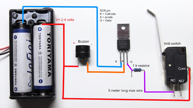
Hello, today I will show you how to make a security door alarm, the door alarm is easy to make and give the best result. The door security alarm provides a very long battery life and easy installation, the circuit use only 2.4 volts to operate so you can power the circuit with 2xAA rechargeable battery or even you can use a lithium-ion battery with auto charging circuit as power supply because the circuit can withstand up to 5 volts power supply. If you want to change the power supply to 12 volts, you simply need 7805 IC to regulate 12 volts to 5 volts without any problem. You also can use 12 volts Buzzer instead 5 volts Buzzer that I used in the circuit and connect directly to 12 volts power supply (solar charger's output, 12 volts car battery). The SCR (thyristor) in this circuit can withstand current up to 3 A so you can connect 20 Buzzers (estimate 100 milliamp/hour per Buzzer) with one circuit module without making any damage to The SCR. You also can ...