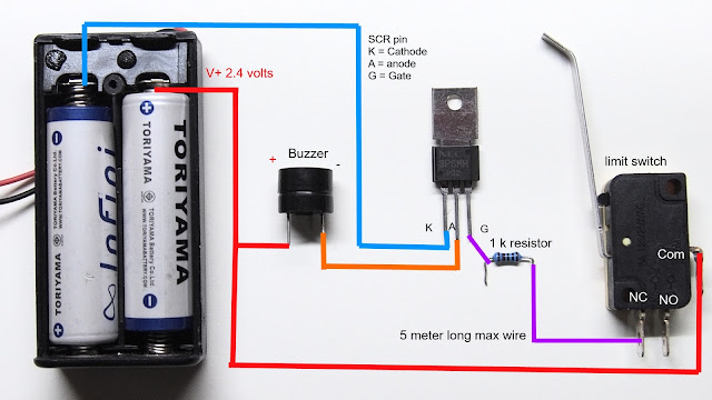
security door alarm circuit diagram
Hello, today I will show you how to make a security door alarm, the door alarm is easy to make and give the best result.
The door security alarm provides a very long battery life and easy installation, the circuit use only 2.4 volts to operate so you can power the circuit with 2xAA rechargeable battery or even you can use a lithium-ion battery with auto charging circuit as power supply because the circuit can withstand up to 5 volts power supply.
If you want to change the power supply to 12 volts, you simply need 7805 IC to regulate 12 volts to 5 volts without any problem. You also can use 12 volts Buzzer instead 5 volts Buzzer that I used in the circuit and connect directly to 12 volts power supply (solar charger's output, 12 volts car battery).
The SCR (thyristor) in this circuit can withstand current up to 3 A so you can connect 20 Buzzers (estimate 100 milliamp/hour per Buzzer) with one circuit module without making any damage to The SCR. You also can change the SCR model if you want smaller circuit.
Component list
5 volts Buzzer
1 kilo-ohms resistor
3 leg limit switch
SCR 3p6mh (You can use another SCR model without any problem just check K, A, G pin is correctly used)
Door security alarm circuit diagram
Door security alarm working and circuit explain
Feel free to ask any question about my project in comment box below


This comment has been removed by a blog administrator.
ReplyDelete