simple bass booster circuit diagram
This bass boost diagram is easy to build and work well, I made it because people asked me the schematic diagram of bass boost diagram on my youtube channel.
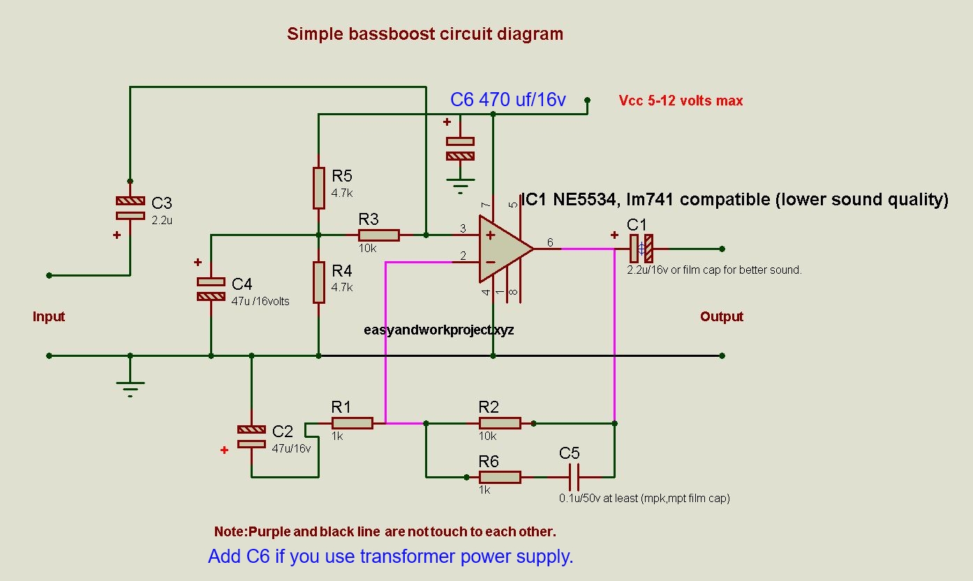
The circuit has 9 dB gain@40 Hz that mean you will get good bass performance even you play music to a small speaker.
Why this circuit doesn't look like circuits on the internet?
Almost every circuit on the internet uses R/C filter between pre-amp and power amp stage to bypass high frequency to a ground and that seems audio signal being amplified and bypass to ground. I think it wastes pre-amplifier gain, the more gain preamp stage the more distortion to the audio signal, so I use a capacitor to send more negative feedback to pre-amp negative input when the frequency higher than cut-off frequency, capacitor impedance(resistance) higher when frequency lower and that make negative feedback decrease when frequency lower.
An op-amp distortion lowers when negative feedback higher, that mean high-frequency distortion lower when you use this circuit because frequency over cut-off frequency's total harmonic distortion being suppressed around 20 DBs more than normal R/C filter.
The C5 cap can be replaced with MKP type or polystyrene film cap with 1% Precision for the best result.
List of component:
potentiometer = 10 kilo-ohms
IC1 ne5534 (you can use another opamp that pin compatible to the ic)
R1,R6 = 1 kilo-ohms
R2,R3 =10 kilo-ohms
R4,R5 = 4.7 kilo-ohms
C1,C3 = 2.2 uf 16 volts
C2,C4 = 47 uf 16 volts at least (no more than 100 uf)
C5 = 0.1 uf
C5 value can be change depend on your listening behavior
0.1uf = + 15dB(gain = 6 times)@159 Hz and + 17.84dB(gain = 7.8 times)@80 Hz and then + 19.39dB(gain = 9.33 times)@40 Hz good for very small speaker, 2 way car speaker
0.2 uf = + 15dB(gain = 6 times)@80 Hz good for small speaker
0.4uf = +15dB(gain = 6 times)@40 Hz good for someone that love deep bass boost and big speaker
See testing video


Sir, Can i use 'HA17741 OP-AMP? & Resistor Wattage? Can i attach this bass booster to the input of 'PAM8610 AMPLIFIER BOARD?
ReplyDeleteYes, you can.
DeleteNew question and thanks for the clarification that the potentiometer is simply in series with the output of your mp3 player/input of your circuit (but please when you have a chance update the schematic to reflect his).
ReplyDeleteAnyways,
I am using an OPA627 OP-AMP with ALL Solen metallized Polypropylene Capacitors (stuff I had laying around and some new one's off of Madisound).
Can I simply run my OP-AMP with a differential +ve & -ve 15VDC supplies ? Your circuit is running single ended with -Vs tied to ground.
In theory, this should work without having to change anything else in your schematic.
Thanks in advance,
Joe
I 've answer your question on my Facebook page already.
DeleteSir could pls give block diagram and working for this circuit?
ReplyDeleteFirst picture is block diagram.
Delete