Posts

Showing posts from 2016

How to make a DC power supply for your amplifier

Image
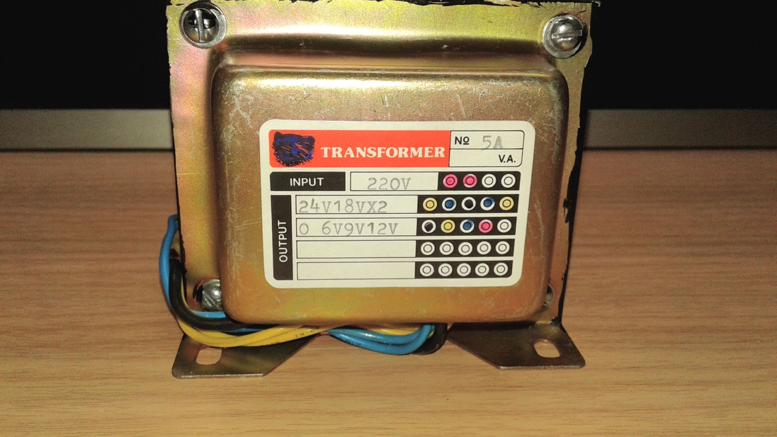
Hello, today I will show you how to make a DC power supply for your amplifier project. An audio amplifier normally needs DC power supply to feed it so you need to know how to make it if you want to make a good amplifier. Now, let's start. 1. Find your amplifier's recommended voltage. I use TA2024 amplifier board, the amp board recommends voltage is 8.5 - 13.2 volts so I need a DC power supply that output voltage does not exceed 13.2 volts. 2 Find the right transformer for your project. When you convert AC to DC with full bridge diode rectifier, the DC voltage increase around 1.4142 - 0.6 volts from an AC input when DC output doesn't connect to a load. I found the formula on the internet and it is AC x 1.4142 only but it was not same as I measured because the DC output voltage decreases around 0.6 volts. The transformer on the above picture provide 9.65 volts AC without connecting to a load, the voltage will drop when you connect to a load. So t

Automatic night light switch project

Image
Hello, today I'm going to show you how to make automatic night light switch. This circuit is easy to make and uses few electronic components. This automatic night light switch project makes you save your electricity bill and makes your light bulb life longer. The circuit uses 5 volts power supply so you can use old USB cell phone charger as a power source or you can use any 5 volts adapter that rate at least 100 mAh.  Electronic components list: BD139 npn transistor = 1 BD140 pnp transistor = 1 100 kilo-ohms resistor = 2 5Volts@100 mAh adapter 1 kilo-ohms resistor = 1 Led = 1 ( you can remove 1 kilo-ohms resistor and LED if you don't need LED indicator) 1 LDR (light dependent resistor) = 1 5 volts Relay = 1 All resistor are 1/4 watts rating Full wiring diagram Circuit explains: BD 140 is a PNP transistor that amplifies small current from 2 x 100 kilo-ohms resistor and sending current to  BD 139 NPN transistor Base (B) and amplifies current

Resistor color code

Image
A resistor is the most important electrical component in almost every electronic circuit, it can limit current to any load such as led, transistor, op-amp, etc.  We must read the resistor color code if we want to know the resistive value, tolerance, temperature coefficient. Resistors have different color bands (3,4,5,6) the more color bands the more resistor information. Now let's start with 3 bands resistor color code. The above resistor has only 3 bands First digit, Second digit, and multiply. A 3 bands resistor color code has a fixed +/- 20% tolerance which means if the color code value is 1,000 ohms the real-life resistive value may be +/- 200 ohms.  4 band resistor color code A 4 bands resistor color code has a tolerance value color strip, the resistor on the above picture has 5% tolerance. This type of resistor uses in a regular circuit such as television, radio, washing machine. 5 bands resistor color code A 5 bands resistor color codes have th

DIY toggle touch sensitive switch

Image
Hello everyone, today I'm going to show you how to make a touch sensitive switch, the switch makes you control light,motor just by touch the switch. The switch is very long life and safe to operate even your hand wet because you can put the touch sensor behind any plastic plate and make a touch sensitive light switch or you even can put the circuit in a lamp and make a touch lamp. This circuit uses CD4013BE d flip-flop IC . When you touch the touch sensor( The red module on the above picture) The sensor send output high to CD4013BE pin3 and make CD4013BE pin 1 change state to on or off once. However, CD4013BE output current not high enough for a relay to operate(yellow-black box on the above picture) so you need a PNP transistor(BD140) to amplify current for a relay. You can remove R4 and LED if you don't need light indicator in your project. This circuit uses 5 volts DC to operate so you need a transformer and it cause your overall circuit big but you can buy a ti

how to make a website

Image
Hello, everyone. I'm going to show you the easiest ways to create your own website, you don't need to know deeply Html PHP or another complicated website code and you don't need to pay much money to make it. You Blogger | Free for life Sign up your google account and paste this address into your browser's address bar  https://www.google.co.th/intl/en/about/products/  and click Blogger. Now, you are on blogger page, it's time to create a website. All you have to do is simply click New blog icon as shown in an image below. Choose your website title, a website's address, and website template. Now, start writing your first post by click New post. Write a little and add Label(it's work like a tag in WordPress) and click publish. Now your first website is online. However, free website template from blogger is not the best template you can download free blogger template on the internet and follow my instruction below. Find bl

how to take a screenshot on PC

Image
Hello everyone, today I'm going to show you how to take a screenshot on a PC (windows10). The methods are  easy and you don't need to install third-party software. Method 1 | Use Window key + Print Screen This method is the easiest way to capture screenshot on a PC but you can't adjust anything such as file type, capture area so you need to edit image size and area in photo editor software again. Window key and Print Screen key Method 2 | Use snipping tool software (Factory software on Windows 7 to 10) Sometimes you may don't know that windows 7-10 have a Snipping tool software, you can use the software to capture any content that shows on your computer screen and save it as png, gif or jpeg file. You can also choose an area that you want to capture such as Free-form, Rectangular, window or the whole screen. All you have to do is just click window key + S and type snipping and click the program. Snipping tool software Easyandworkproject.xyz

How to use a breadboard for your project

Image
A breadboard is a useful tool that makes any electronic project easier, you don't need to solder electronic component like prototype board, all you can do are just connect an electronic component to a breadboard and see your project working. However, I saw comments on my youtube channel that they did not know how to use a breadboard but they can read schematic diagram!!! I'm not a fan of simulation software because I was using the software to simulated amplifier IC circuit and it did not work but everything works fine when I use the same circuit in a breadboard. Two picture below is a breadboard and wiring inside it. The red line for positive polarity, the Black line for negative polarity, orange lines is connected. Another column is same as the orange column.  A DIY beginner may confuse and connect electronic component wrong and make circuit not working. See the wrong way to connect electronic component on a breadboard. As you can see the picture below, th

1kHz to 24 kHz | High frequency sine wave test tone

Image
High-frequency sine wave speaker test tone from 1 kHz to 24 kHz for an audio lover who want to test his/her sound system and hearing ability vs frequency. Each frequency duration is 3 seconds. The video contains wave pattern too. If you use this video as hearing test tone you must use good quality headphones or hi-fi sound system because laptop loudspeaker frequency responds not good both low and high frequencies Play video below by set video quality to Full HD for the best result. BEWARE: LOWER YOUR VOLUME FIRST!!!

How to remove scratches from your eyeglasses (hard core version) no cut scene!!!!

Image
I saw many ppl ask before and after pictures in my previous "how to remove scratches from eyeglasses" video, so I decided to upload no doubt and clear method. The eyeglasses lens I used in this video was severely full of scratches because I wipe multicoat with sand paper so you can see the progress very clearly. This method not just for eyeglasses but good for another plastic material too. You can use any soft car wax in the market to rub your eyeglasses but water is the key to making it done. All you need is -soft car wax -microfiber cloth -water -time. I also saw people comment that this method not working so I will tell the secret.(... patience is the key to success...)

How to make a simple audio pre-amplifier

Image
I saw a comment on my video that he wants a high-gain audio amplifier (1000 times or 60 dB voltage gain!!!). However, most commercial power amplifier IC has a maximum fix gain of around 200 times (lm386) which is far from 1000 times voltage gain, and the problem when you make a high gain amplifier is the high-frequency roll-off problem. The solution to the problem is making a pre-amplifier that has very low distortion, and wide bandwidth, and it can amplify audio signal around 10 times or 20 Dbs and send the audio signal to a power amplifier (the power amp IC he uses is tda7052 that has 40 dB or 100 times voltage gain). When combining the voltage gain of the two amplifiers, he will get 1000 times the voltage gain audio amplifier!!! The method is easy and uses minimum electronic components Breadboard wiring Audio preamplifier circuit diagram. Electronics component list: IC 1 = NE5534(op amp ic) R1, R2, C3 are amplifier gain control by negative feedback, the fo

Arduino project | how to make a contactless thermometer

Image
This Arduino project: a contactless thermometer is good for anyone who wants to measure temperature from any object without touching it. The infrared sensor detects infrared radiation that is emitted from an object and converts the value to digital data and sent the data to the Arduino board via an I2C interface.  The sensor I use in this project is mlx90614, an infrared and ambient temperature sensor. It can measure a wide range of temperature from -70 to 380 °C for object temperature  reading  and the sensor also measure ambient temperature from -40 to 125°C.  Mlx90614 module read an object temperature and ambient temperature and sends both outputs at the same time.  The sensor module cost around 3 - 4 $ from eBay free shipping   worldwide!!! All you need for this project are Arduino unoR3,mlx90614 module,20x4 I2C display, and jumper wire. Below is the temperature sensor wiring diagram:   MLX90614 wiring diagram   VDD ------------------ 3.3V   VSS -------