How to use a breadboard for your project
A breadboard is a useful tool that makes any electronic project easier, you don't need to solder electronic component like prototype board, all you can do are just connect an electronic component to a breadboard and see your project working.
However, I saw comments on my youtube channel that they did not know how to use a breadboard but they can read schematic diagram!!! I'm not a fan of simulation software because I was using the software to simulated amplifier IC circuit and it did not work but everything works fine when I use the same circuit in a breadboard.
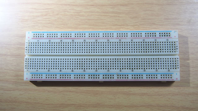
Two picture below is a breadboard and wiring inside it.
 |
| The red line for positive polarity, the Black line for negative polarity, orange lines is connected. Another column is same as the orange column. |
A DIY beginner may confuse and connect electronic component wrong and make circuit not working. See the wrong way to connect electronic component on a breadboard. As you can see the picture below, the IC pin 1-14,2-13,3-12,4-11,5-10,6-9,7-8 are short to each other.
The below picture is right way to connect the IC
Now, you know how to use a breadboard. However, a breadboard not a perfect tool, your project may have strong noise when you test high gain amplifier IC but you can decrease noise with R/C filter.
Enjoy DIY electronic's world!!!



Comments
Post a Comment