Posts

Showing posts with the label learn electronics

simplest off delay timer

Image
Hello, I will show you how to make an off-timer delay. This circuit is simple and uses only 3 electronic components. The off time of this circuit is around 15 seconds. But you can change the R-value to increase or decrease off time. Let's make it like the below video.

The simplest fan speed control circuit diagram

Image
Hello, today I will show you how to make a simple fan speed control by just 3 electronic components I use only 3 parts One is a 10 kilo-ohms resistor An IRF540N NPN MOSFET and a 10 kilo-ohms potentiometer No heatsink require for less than 2 A load  I use a MOSFET instead of a transistor because a MOSFET control input by voltage so it's easy to bias Let's start by connecting the resistor to the positive terminal and connect another leg to a MOSFET gate connect a MOSFET gate pin to a 10 kilo-ohms potentiometer. two resistor works as a voltage divider connect a MOSFET drain pin to the ground and also connect the potentiometer middle leg to the ground This circuit use only two legs of a potentiometer Then connect a source pin to the load negative pin and connect the load positive pin to 12 volt or positive terminal. See the video below for practical use.

How to make a DC power supply for your amplifier

Image
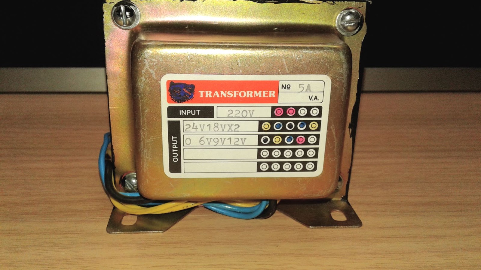
Hello, today I will show you how to make a DC power supply for your amplifier project. An audio amplifier normally needs DC power supply to feed it so you need to know how to make it if you want to make a good amplifier. Now, let's start. 1. Find your amplifier's recommended voltage. I use TA2024 amplifier board, the amp board recommends voltage is 8.5 - 13.2 volts so I need a DC power supply that output voltage does not exceed 13.2 volts. 2 Find the right transformer for your project. When you convert AC to DC with full bridge diode rectifier, the DC voltage increase around 1.4142 - 0.6 volts from an AC input when DC output doesn't connect to a load. I found the formula on the internet and it is AC x 1.4142 only but it was not same as I measured because the DC output voltage decreases around 0.6 volts. The transformer on the above picture provide 9.65 volts AC without connecting to a load, the voltage will drop when you connect to a load. So t...

Resistor color code

Image
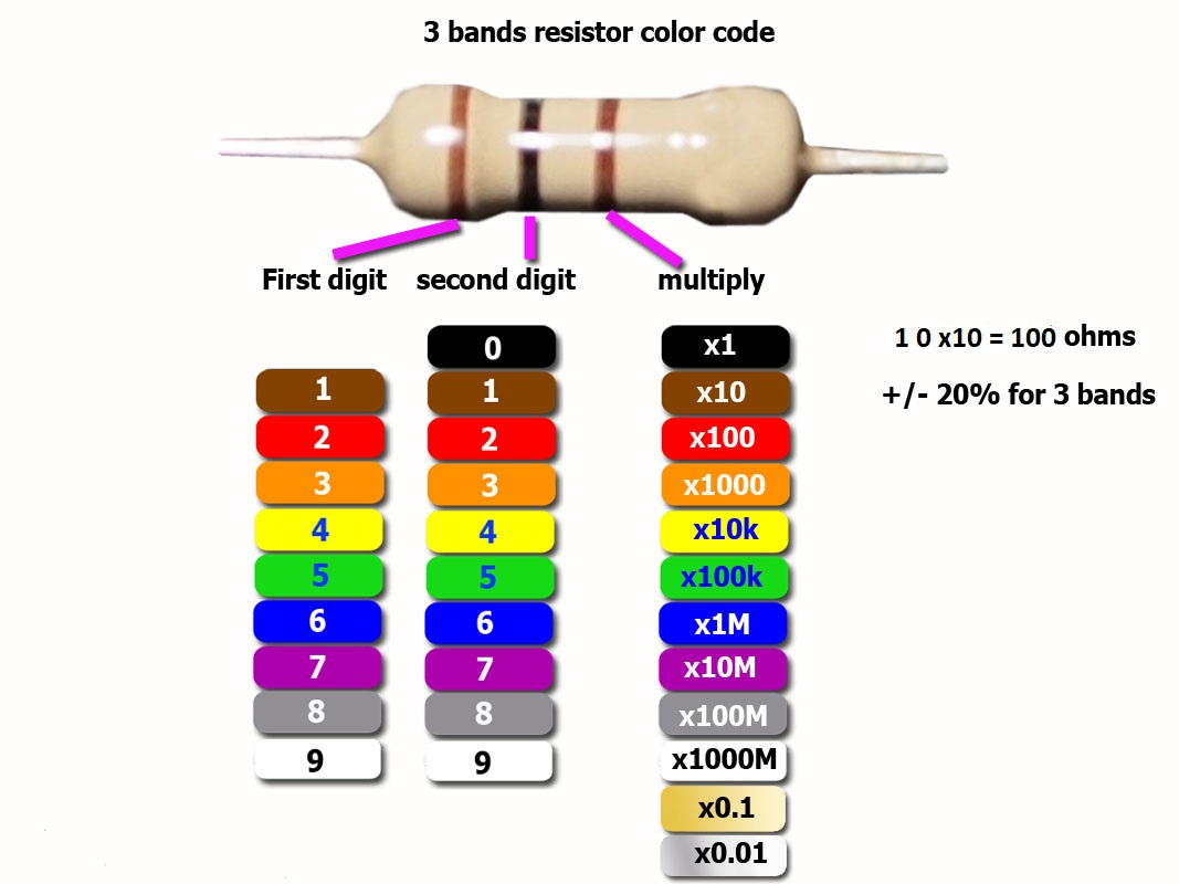
A resistor is the most important electrical component in almost every electronic circuit, it can limit current to any load such as led, transistor, op-amp, etc.  We must read the resistor color code if we want to know the resistive value, tolerance, temperature coefficient. Resistors have different color bands (3,4,5,6) the more color bands the more resistor information. Now let's start with 3 bands resistor color code. The above resistor has only 3 bands First digit, Second digit, and multiply. A 3 bands resistor color code has a fixed +/- 20% tolerance which means if the color code value is 1,000 ohms the real-life resistive value may be +/- 200 ohms.  4 band resistor color code A 4 bands resistor color code has a tolerance value color strip, the resistor on the above picture has 5% tolerance. This type of resistor uses in a regular circuit such as television, radio, washing machine. 5 bands resistor color code A 5 bands resistor colo...

How to use a breadboard for your project

Image
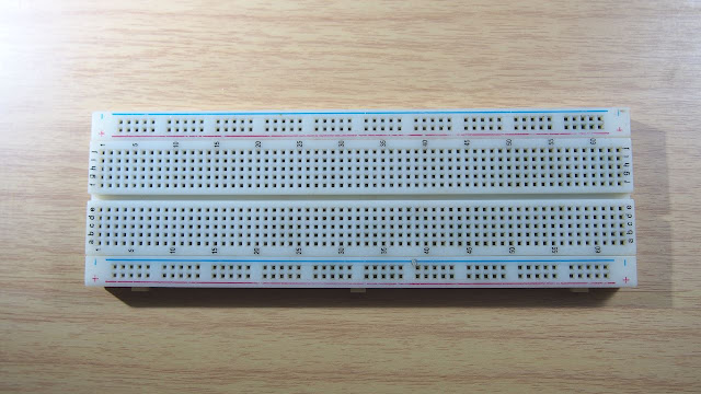
A breadboard is a useful tool that makes any electronic project easier, you don't need to solder electronic component like prototype board, all you can do are just connect an electronic component to a breadboard and see your project working. However, I saw comments on my youtube channel that they did not know how to use a breadboard but they can read schematic diagram!!! I'm not a fan of simulation software because I was using the software to simulated amplifier IC circuit and it did not work but everything works fine when I use the same circuit in a breadboard. Two picture below is a breadboard and wiring inside it. The red line for positive polarity, the Black line for negative polarity, orange lines is connected. Another column is same as the orange column.  A DIY beginner may confuse and connect electronic component wrong and make circuit not working. See the wrong way to connect electronic component on a breadboard. As you can see the picture below, t...

how to use a digital multimeter

Image
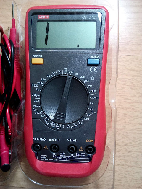
A multimeter is a tool that uses to measures electrical characteristic such as voltage, ampere, resistance. Using a multimeter and basic knowledge of ohm's law can help electronics projects much easier. There is two type of multimeter one is a digital multimeter and another is an analog multimeter. The advantage of digital multimeter is easy to read value, lower power consumption, and higher price model can measure diode, capacitance, frequency, duty cycle, inductance, the temperature you can call it all in one multimeter instead of a multimeter. How does a multimeter work? Basic functions of multimeter are measure voltage, ampere, and resistance. A multimeter changes electrical characteristic values to numbers for digital multimeter or meter scale for an analog multimeter. What type of multimeter you need: - If your project involves high dc current you must use high DC current type multimeter, the high current multimeter probe usually bigger and have separ...