Posts

Showing posts from March, 2018

Humidity sensor with led alarm | Arduino project

Image
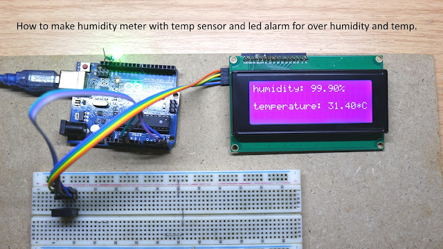
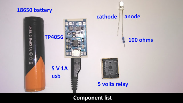
This page contains Arduino Humidity sensor with led alarm source code. This project is good for someone who wants to make a humidity meter or hygrometer with led alarm if humidity and temperature over a threshold. It's easy to make and doesn't require an external power supply, just use power from an Arduino UNO R3 board (USB power compatible with this project). Electronic components list: 1 x Arduino Uno R3 1x 20 x4 I2C LCD display 1 x AM 2320 humidity/temp sensor 1 x 5 mm led ( 2 x if you plan to use led for pin 13 instead built-in led) 1 x 1000 ohms resistor ( 2 x if you plan to use led for pin 13 instead built-in led) Any USB power adapter, 500 mA current at least. Here is the Arduino code: AM 2320 library  https://github.com/hibikiledo/AM2320 LCD display i2c library  https://github.com/fdebrabander/Arduino-LiquidCrystal-I2C-library #include <Wire.h> #include <AM2320.h> #include <LiquidCrystal_I2C.h> LiquidCrystal_I2C lcd(0x3F, 20, 4);

How to make an emergency led light

Image
This video shows you how to make an emergency light, it is the very important thing when a 110/220 AC power failure. This circuit will make your life better!!! This emergency led light project use minimal electronic components and can work over 10 hours and recharge automatically. The circuit uses USB power supply so you can use old smartphone adapter as power supply, 5 volts, and 1 Ampere is the minimum required for this circuit. Electronic component list: 1 x  18650 Li-ion battery 1 x TP 4056 Li-ion battery charger module 1 x 5 volts relay 1 - 10 x 100 ohms resistor 1 - 10 x low current white led (another color is ok but white led is the best) 5 volts 1 Ampere USB type c adapter Real electronic components picture After you got all the electronic components I listed above, it's time to make the circuit by watching my video. This circuit has a very long life, all you need to change is 18650 battery(many years). You may need to recharge the batter

How to build high current hall effect sensor

Image
I published hall effect sensor circuit diagram and my audience asked me how to make a hall effect sensor that has a high current capability, so I made it for him and for all of you who want to build high current hall effect sensor. Normally, hall effect sensor used for detect magnetic field and send output to a microcontroller, that means any hall effect sensor doesn't need to have high current output. However, if you want to drive motor or any high current device without a microcontroller, this circuit is the best for you. List of components for this project: 1 x IRF 9540N (P channel MOSFET) 1 x A3144 hall effect sensor 1 x 1 kilo-ohms resistor 1 x 10 kilo-ohms resistor optional (use for led indicator) 1 x 1 kilo-ohms resistor 1 x White, red, blue or any other low current led Note: all resistor for this circuit is 1/4 watt, 20 % tolerance is ok with this circuit. The principle of this circuit: When hall effect sensor detects magnetic