How to build high current hall effect sensor
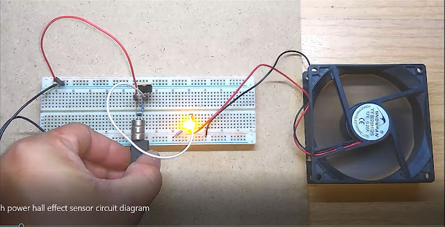
I published hall effect sensor circuit diagram and my audience asked me how to make a hall effect sensor that has a high current capability, so I made it for him and for all of you who want to build high current hall effect sensor.
Normally, hall effect sensor used for detect magnetic field and send output to a microcontroller, that means any hall effect sensor doesn't need to have high current output. However, if you want to drive motor or any high current device without a microcontroller, this circuit is the best for you.
List of components for this project:
1 x IRF 9540N (P channel MOSFET)
1 x A3144 hall effect sensor
1 x 1 kilo-ohms resistor
1 x 10 kilo-ohms resistor
optional (use for led indicator)
1 x 1 kilo-ohms resistor
1 x White, red, blue or any other low current led
Note: all resistor for this circuit is 1/4 watt, 20 % tolerance is ok with this circuit.
The principle of this circuit:
When hall effect sensor detects magnetic field, it sends output low (0 volts) to P channel Mosfet.
P channel Mosfet starts to conduct current when Gate pin has lower voltage potential than Source pin.
Mosfet is a voltage control device so it is easy to drive a Mosfet with low output current sensor like hall effect sensor, light sensor.



Comments
Post a Comment