Hall effect sensor wiring diagram and test video
Hall effect sensor switch is a switch that turns on when enough magnetic field near the IC. You can use hall effect sensor to make many Diy projects such as rpm meter, magnet detector, and more project involves with a magnet.
Did you know? Hall effect sensor uses in many electric machines, example; when you open washing machine door and the machine stop spinning, or when you open microwave door then it pauses and send beeping sound until you close the door.
Hall effect sensor IC in this post is A3144(old component but work well and low cost) Send output low (0 volts) when strong magnetic field near a sensor, that why somebody asked on the internet why his project involves hall effect sensor didn't work.
 |
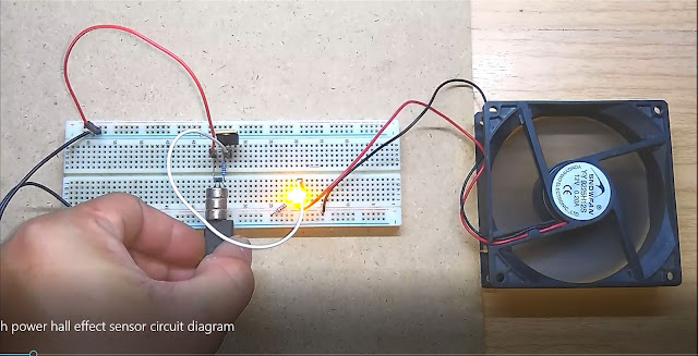
| Hall effect sensor wiring diagram. |
You can see an above image that a load(LED in this picture) connect to positive electrode and output instead output and ground. That's the reason why some projects don't work and will never work because the output low when magnet near the IC
If you want to use hall effect sensor with Arduino board, you must add 10 kilo-ohms resistor between a positive electrode and an output of hall effect sensor to make the output from IC high (5 volts).
Note: 1 kilo-ohms resistor use as a current limiter for an LED you can lower value if you want an LED brighter.


Yes, the output (pin 3) is connected to the LED's cathode. But the photo shows it connected to the anode (the long pin) of the LED with the cathode (short pin) connected to Vcc. Reverse the LED in the photo.
ReplyDeleteSorry to reply toooo late. The LED's cathode pin in the picture is correct(flat at bottom side of LED) but I cut the LED's leg because I used it with another project too.
Delete