Infrared proximity sensor circuit diagram
An infrared proximity sensor is a sensor that detects any object when it close to the sensor. The circuit is an important part of an automatic faucet, robot, and touchless switch.

An above image is an infrared proximity sensor circuit diagram. The circuit is simple and easy to make, it has 2 transistors, 4 resistors, an IR LED, an IR phototransistor, and a purple or white or green LED (use as an indicator so you can remove it if you want)
Electronic components list

This circuit's maximum detection range is 10 centimeters, you can decrease the detector range by changing R2 resistor. Use 7805 regulator IC if you want to use the circuit with 12 volts power supply.
The infrared proximity sensor consumes around 50 milliamps per hour when standby and consumes around 80 milliamps(add a relay that consumes 30 milliamps) so you need an external power supply because battery life will not last long. The reason that makes this circuit consume much energy because IR LED need at least 50 milliamps to make IR light strong enough for an IR Sensor.
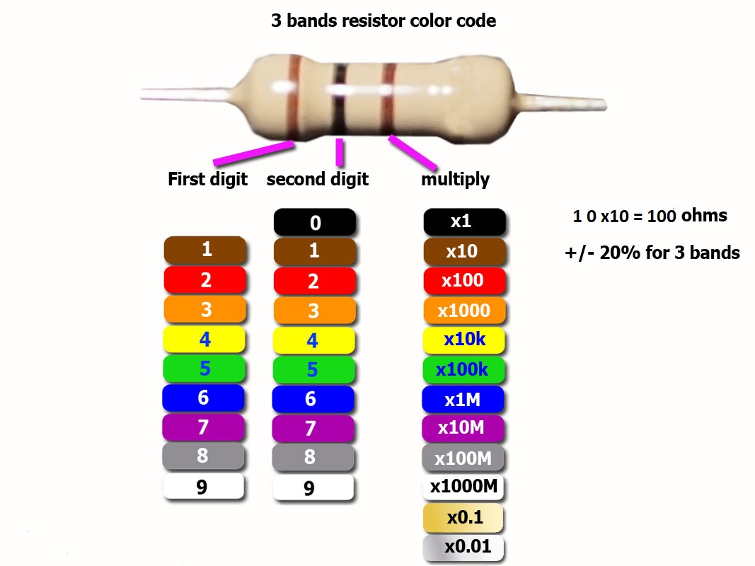
If you're not familiar with resistor color code see how to read it here
Proximity sensor circuit diagram

The red line does not touch the purple line so be careful.
Note: another leg of R2 connect to Vcc, Replace it with 50 K variable resistor if you want to adjust the sensor range.
Note: another leg of R2 connect to Vcc, Replace it with 50 K variable resistor if you want to adjust the sensor range.
See testing video (set video to 720p if the content missing)


Does the sensor have round circular, or straight line sensing ability?
ReplyDeleteThe IR led has a round circular detection but the best spot is on the center of the sensor.
Delete