How to connect volume control to an amplifier
I saw a comment on my Youtube video, he asked me how to connect any amplifier module to a volume control or potentiometer. I think so many people who want to start an electronic project must know this basic wiring too, I hope this wiring diagram will help an electronic DIYer like me.
First thing you need to know:
- use shield wire for an input signal to volume control and from volume control to amplifier if you don't want you amplifier suffers from parasitic oscillation (sound like JeeeeJeeeee).
- keep a wiring as short as possible.
- use low resistive value volume control (5-10 kilo-ohms) if the amplifier has random parasitic noise when you turn a volume control up or down.
- volume control is a potentiometer.
You can see I use a capacitor to block DC current to an amplifier input, but if you use board amplifier you shouldn't use the blocking capacitor because a board amplifier module(pam9610,pam8403,ta2024 as reference) always attaches the input D.C. blocking capacitor in an amplifier module.
What is an input D.C. blocking capacitor value?
You can use 1 microfarad, 16 volts, in some case increase or decrease input capacitor value can make sound different. If you use a lower value such as 0.47 microfarad you will hear sound brighter but less bass, so you can change the value that suits your listening style.
Where is the input of an amplifier module?
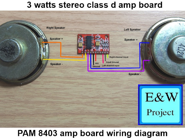
Below picture shows the input of an amplifier board
This is PAM 8610 board has two channel (stereo), you can see two input but one ground.
See the first picture and you will see a ground from a signal source, that is the ground you connect to an amplifier board. As I explain above you can eliminate D.C. blocking capacitor because PAM 8610 board has the onboard-dc-blocking capacitors.
You can use a volume control output as the yellow mark in the first picture connect to Left or right channel input on the amplifier board, you must use twin channel volume control for a two-channel amplifier for better sound, and frequency respond.
If you need your amplifier board more sensitivity, you can make preamplifier that boost 10 times voltage gain for you project here >>> How to make simple preamplifier


hi,, which it is the value of the capacitors?
ReplyDeleteYou can use 1 micro farad capacitor, voltages at least 16 Volts. You also can use film type capacitor that has better audio performance but size are very bigger.
Deletehello Phethai,
ReplyDeleteyou have amazing post about electronics , many people seearch this. Im an electronics hobyist.
Thanks for sharing.
Visit my site also at www.elcircuit.com
Thank you.
ReplyDeleteaccording with pam8610 datasheet, this chip have a pin for volume. but some manufactors dont use it. can u make a volume for this native voloume pin?
ReplyDeleteVery informative thread Phethai..I want to use this amp with my guitar...output of guitar is obviously mono...can I join +ve with both left and right input of this circuit and -ve with the ground so that I get output on both left and right speakers...??
ReplyDeleteYou can join both amplifier channels input (L and R) and connect it to guitar output without any problem and connect ground to the guitar output ground.
DeleteJoin +ve to left and right input of this circuit make amplifier destroyed, don't do it!!!
Thanks for your response friend...I am not expert in electronics...I find both of the above situations explained by you the same..please explain..also please confirm whether it is safe joining input L&R of amp circuit..afterwards connecting guitar's ground to amp's ground and guitars phase to joined input LR.
ReplyDeletepower amplifier input impedance very high, if the power amplifier input(L R) use the same ground, you can join both input without any problem.
DeleteSecond answer: You need an XLR preamplifier, so you can't connect the XLR output to a power amplifier directly.
Bro can we do something like connecting 2 amplifier module from one input source
ReplyDeleteIt's easy, just connect each amplifier module to each DC blocking cap and connect another DC blocking cap leg(both of them) to volume control output on the first picture in this page(yellow line, remove DC blocking cap in the first picture).
DeleteA power amplifier module input resistance is very high ( 30 kilo-ohms to fews mega-ohms or more with a j-fet input amplifier) and normally the AV/line out audio source resistance is around 10 kilo-ohms, so you can parallel input of power amplifier module without any problem (depending on input resistance of the power amplifier module).
I am dying on a similar project.
ReplyDeleteI am using a regulated 12v power supply(external) to power several little items rigged up in a wood cabinet. I am well within the mAh rating of the p/s. There are speakers mounted on either side of the box so I am thinking the amp is picking up signal interference...I am using shielded 26 gauge wire. When I have the components laid out on my bench far apart it seems to work fine but when in the box they just grumble and static and pop. I have checked and rechecked wiring and connections. What can be done to shield a amp board?
ALSO on a related note, I am including a A250k log pot to control audio. I join the left and right together on the amp and on the input port and wire it as above but the audio is static and poppy and no adjustment seems to come from the pot. It may be the interference that I mentioned before...but maybe I am missing something.
Any thoughts as to what that might be?
I am using a 10uf cap between the pot and the amp...just does not seem to work. My next attempt will be to join the output channels to make it mono and try the pot there...but before I did I thought I would ask.
separate power supply wire from input wires.
DeleteHocam merhaba ben Türkiye'den çok teşekkür ederim bilgilendirme için çalıştı gerçekten
ReplyDeleterica ederim
Delete