Posts

Showing posts with the label audio amplifier circuit diagram

How to improve bookshelf loudspeaker sound

Image
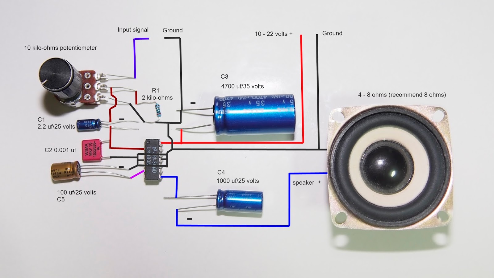
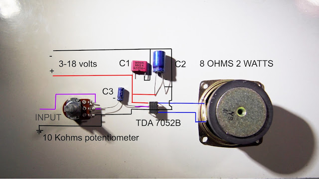
 My audience on my youtube channel asked me how to find a crossover network capacitance and inductance so I will make it here The speaker I made crossover network is a microlab b77. The speaker lacked the woofer's crossover network, no absorbent so I fixed it for cleaner sound and changed the tweeter's high pass filter to a better one. Step 1 Change the old capacitor to a metalized polypropylene capacitor (very clean sound). The capacitor value is 4 uf and the speaker is 8 ohms so the crossover frequency =1/6.28x8x4 = 0.004976 x 1,000,000 = 4976 Hz (x1,000,000 come from Farad to microfarad) If you want to find crossover frequency C= 0.1590/(R x F) x 1,000,000 for uf Step 2 Find induction for the woofer. L = .1592 x 4(woofer resistance)/4976(Hz) =1270 micro Henry x1000 = 0.127 mH but I has 0.1 mH so the crossover point may change a little but not much. If you want the complete sound you may find 0.127 mH Speaker crossover diagram. Step3 Add absorbent to the speaker cabinet. The ...

The simplest 12 volts led dimmer circuit diagram

Image
This page shows you how to make the simplest 12 volts led bulb, the led bulb that uses with solar cell or 12 volts adapter.  Why you should use 12 volts led bulb? The simple answer is the 12 volts led bulb doesn't have any flicker that makes your  Eye fatigue. This is the schematic diagram of this project This circuit is simple to make and very safe because the 7805 IC has short circuit protection, over current protection, thermal protection so this circuit is good for beginner to advance electronic DIYer. See the working circuit from the video below. If you love this project, please support us by Share this page to your friends.

Simple class a audio amplifier circuit diagram

Image
This post shows a video about how to make a simple class a single-ended(the most transparent sound amplifier circuit). The circuit has low output power because I want to make the audio amplifier that sounds good but not generate to much heat to my room(class a generate heat even it stay idle). The first part in this video is a sound test and a circuit is last. 😊 The amplifier has a low output impedance because of high negative feedback from op amp and also lower THD. The disadvantage of this circuit is it has low power, so you must find high sensitivity speaker if you want high sound volume and it not good for an action movie. This circuit draw current from op amp around 12 mA (according to lm 4562 datasheet) but if increase bias current at output state it may draw more current from the op amp because the op amp negative feedback try to maintain output to match non inverting input voltage reference. see the video here see the method to connect power amp input to volume cont...

Combine 3 speakers to one amplifier

Image
I saw a question in my Youtube video about how to combine speakers for one amplifier unit without making any damage to an amplifier.  An speaker impedance must be match or higher than an amplifier manufacturer specification, if you use lower speaker impedance than an amplifier specification, your amplifier may end up damaged or make a fire when you play loud music. A commercial amplifier can handle between 4 - 16 ohms speaker impedance and maybe lower to 2 ohms for car subwoofer amplifier. but in a question, he asked me how to combine 3 speakers @ 6 ohms load to one amplifier. The simple solution is to make 3 separate amplifiers and share same input, but it makes the circuit more complicated and uses many electronic components. However, if connect all 3 speakers in series, it will make impedance equal to 18 ohms and it makes an amplifier output drop so much. So, I use 2 speakers connect in parallel and series to other speakers like an image below SP 1 and SP 2...

5 watts amplifier TDA7056A wiring diagram

Image
TDA 7056 A is an audio power amplifier IC that has 5 watts output power with 8 ohms speaker and 3 watts with 16 ohms speaker. The IC is simple to wiring and needs only 6 external components to make the amplifier working. TDA 7056A working with a power supply between 4.5 - 18 volts so the IC can use a battery as power supply. if you use more than 9 volts, you need to attach small heat sink to the IC. TDA7056A has a built-in DC volume control so you can control the gain of the amplifier by changing voltage value at DC volume control pin by use a potentiometer. DC volume control makes you connect the audio signal directly to the amplifier input so it makes a sound more transparent and cleaner than a normal amplifier.  The IC has a short circuit protection, over temperature protection, No switch-on/off clicks, ESD protected on all pins, Mute mode (The IC switch mode when DC volume control pin voltage lower than 0.3 volts)  TDA 7056A has a very wide audio bandwidth 20 H...

simple bass booster circuit diagram

Image
This bass boost diagram is easy to build and work well, I made it because people asked me the schematic diagram of bass boost diagram on my youtube channel. The circuit has 9 dB gain@40 Hz that mean you will get good bass performance even you play music to a small speaker. Why this circuit doesn't look like circuits on the internet? Almost every circuit on the internet uses R/C filter between pre-amp and power amp stage to bypass high frequency to a ground and that seems audio signal being amplified and bypass to ground. I think it wastes pre-amplifier gain, the more gain preamp stage the more distortion to the audio signal, so I use a capacitor to send more negative feedback to pre-amp negative input when the frequency higher than cut-off frequency, capacitor impedance(resistance) higher when frequency lower and that make negative feedback decrease when frequency lower. An op-amp distortion lowers when negative feedback higher, that mean high-frequency disto...

How to make a DC power supply for your amplifier

Image
Hello, today I will show you how to make a DC power supply for your amplifier project. An audio amplifier normally needs DC power supply to feed it so you need to know how to make it if you want to make a good amplifier. Now, let's start. 1. Find your amplifier's recommended voltage. I use TA2024 amplifier board, the amp board recommends voltage is 8.5 - 13.2 volts so I need a DC power supply that output voltage does not exceed 13.2 volts. 2 Find the right transformer for your project. When you convert AC to DC with full bridge diode rectifier, the DC voltage increase around 1.4142 - 0.6 volts from an AC input when DC output doesn't connect to a load. I found the formula on the internet and it is AC x 1.4142 only but it was not same as I measured because the DC output voltage decreases around 0.6 volts. The transformer on the above picture provide 9.65 volts AC without connecting to a load, the voltage will drop when you connect to a load. So t...

How to make a simple audio pre-amplifier

Image
I saw a comment on my video that he wants a high-gain audio amplifier (1000 times or 60 dB voltage gain!!!). However, most commercial power amplifier IC has a maximum fix gain of around 200 times (lm386) which is far from 1000 times voltage gain, and the problem when you make a high gain amplifier is the high-frequency roll-off problem. The solution to the problem is making a pre-amplifier that has very low distortion, and wide bandwidth, and it can amplify audio signal around 10 times or 20 Dbs and send the audio signal to a power amplifier (the power amp IC he uses is tda7052 that has 40 dB or 100 times voltage gain). When combining the voltage gain of the two amplifiers, he will get 1000 times the voltage gain audio amplifier!!! The method is easy and uses minimum electronic components Breadboard wiring Audio preamplifier circuit diagram. Electronics component list: IC 1 = NE5534(op amp ic) R1, R2, C3 are amplifier gain control by negative feedbac...

how to make condenser microphone pre-amplifier

Image
I saw a comment on my youtube video that he want to connect condenser microphone directly to pam8610 amplifier board. However, if he needs to connect condenser microphone to any amplifier board he must bias and amplify the signal before. Now let's start!!! Condenser microphone need a power supply to bias circuit inside that why we need specific preamplifier for it. You need two electronic component to make condenser microphone to operate  1. 2 to 10 kilo-ohms resistor 2. Capacitor uses to blocking dc current to preamplifier See picture below for better understand. However, an output signal from the microphone is very small and need to amplify with any preamplifier before connecting to amplifier board. Now, let's start making and preamplifier. -------------------------------------------------------------------------------------------------------------------------- Above picture shows how to bias opamp for single power supply (V+ and Ground) ...

PAM 8403 board amp wiring diagram

Image
PAM 8403 is a portable 3 watts stereo class d amplifier that uses only 5 volts D.C. to operate. The amplifier board is easy to wiring and very small size, you can make a small amplifier project that not requires high voltages to work. The first thing you need to know. PAM 8403 cannot bridge together because the amplifier is already bridge-tie-load output configuration Over 6 volts can damage the amplifier module, if you want higher power you can check 10 watts class d amp PAM 8610 here You must use shield wire connect from input source to volume control and from volume control to the amplifier board input if you don't want your amplifier to suffer from parasitic oscillation (sound like JeeeeJeeee) Today I will show you how to wire PAM 8403 board amp that easy to understand. Let's see image below. You can see that two speakers do not share output ground like normal amplifier because PAM 8403 is a  bridge-tied-load amplifier, if each speaker wire touches eac...

How to add power supply filter capacitor to amplifier board.

Image
I saw a new comment on my video, he asked me how to add a filter capacitor to amplifier board D.C. power supply. I think it's a good question so I will explain it here. What is a power supply filter capacitor? It is the capacitor that used to filter AC ripple from DC power supply present to amplifier board. If an amplifier has low capacitive power supply capacitor, it may present a little hum(50/60 Hz low-frequency sound) that you can hear in a quiet room. The capacitor also stores power and bring it instantly to your amplifier when an amplifier needs more power for a short period of time such as  explosion sound in a movie. However, If an amplifier has high-frequency power supply noise from a switching power supply, small capacitor need to parallel to a power supply and must be attached close to power amplifier IC as much as possible. Below pictures are the place that you add power supply capacitor. PAM 8610 board amplifier powe...

How to connect volume control to an amplifier

Image
I saw a comment on my Youtube video, he asked me how to connect any amplifier module to a volume control or potentiometer. I think so many people who want to start an electronic project must know this basic wiring too, I hope this wiring diagram will help an electronic DIYer like me. First thing you need to know: use shield wire for an input signal to volume control and from volume control to amplifier if you don't want you amplifier suffers from parasitic oscillation (sound like JeeeeJeeeee). keep a wiring as short as possible. use low resistive value volume control (5-10 kilo-ohms) if the amplifier has random parasitic noise when you turn a volume control up or down. volume control is a potentiometer. Volume control principle is a signal divider, the more volume control output(yellow line) near input signal source(pink line) the most signal flow to an amplifier. When you lower a volume control the resistive va...

3 watts stereo amp board pam8403 sound test with jvc loudspeaker.

Image
PAM 8403 is a class d integrated amplifier that sounds good and energy efficiency. The ic requires only 5 volts for full 3 watts stereo (2 amperes 5 volts power supply need for full power) with 83 % efficiency @ 4 ohms load, so this amp board is good for battery power. This amp board sound good and fast respond but impact not good as pam8610 (high power version 10 watts stereo) but high frequency seem cleaner. Bass respond not tight(maybe my speakers are oversize) The amplifier board work well with 1-metre speaker cable so this amp is very stable and no need big power supply filter capacitor to eliminate hum from a power supply (Bass respond will be better if you add 2200 uf/16 volts electrolytic capacitor parallel to power supply filter. Make sure you connect electrolytic capacitor with correct polarity!!! or ka-boom.  PAM 8403 specification: - 3W Output at 10% THD with a 4Ω Load and 5V Power Supply - Filterless, Low Quiescent Current and Low EMI - Low THD+N - Sup...

Modified lepy LP-A6fm amp

Image
When I brought lepy LP-A6fm from my local store(Thailand) for under 10 $.  I though it's a good low-cost amp and I've found that this amp not bad at all. The bad thing I hate LP-A6fm is the amp have big pop noise when connecting to the power supply to the amplifier and the amplifier doesn't have any on/off switch. I thought the problem may come from JRC 4558 op-amp that doesn't have soft on/off function so I decided to change JRC 4558 to ne5532 op amp for low pop noise and change some capacitors for sound quality improvement. Yeah! Let's start. List of component: 1 x ne5532 opamp and 8 pins ic socket (for JRC 4558 op amp replacement, sound improve much). 3 x capacitor 100 uf muse FW(FG are better) for op amp power supply replacement and for main amp replacement 4 x 10 uf Elna Ccerafine or Silmic II electrolytic capacitors for the mellower sound. 1 mks 0.1 uf Wima capacitor(not see in the video because it attaches to preamp power supply under PCB board. 2 x...

2.5 watts lm 380n amplifier with stable wiring diagram.

Image
Advantage: 1 Wide supply voltage from 10 to 22 volts so you can use battery power. 2 Use only 8 parts to make jobs done. 3 High bandwidth 100khz 4 Low distortion no more than 3% at 2 watts (not 10% thd at full power like commercial amplifier spec ) Lm380n is old but still good sounding ic if you can eliminate oscillation and power supply ripple. The ic is very easy to build and you don't have to attach heatsink for normal operation. 2.5 watts power is enough to drive small 8 ohms loudspeaker for your little amplifier project. This wiring diagram is very stable and low oscillate noise even your hand near volume control. The cost of lm380n around 1$ R1 is 2 kilo-ohms resistor ( See how to read resistor color code here ) Beware!!!! Capacitor C1,C3,C4,C5 is electrolytic capacitor so you must check polarity or the capacitor especially C3 will explode,that may cause severe injured,so you must know what you do. See this ic sound test video.

tda 7052B full wiring diagram, easy to understand

Image
I accidentally bought IC TDA 7052b from local electronic store (it should be TDA 7052) . I have been finding circuit diagram in google but seem the circuits not working so I decided to test it in my own way. Finally, I found the best wiring diagram that works, so I think I must share it to help DIY lover like me. TDA 7052B is bridge-tie load amplifier ic, so no need output capacitor coupling (Better bass respond and bass quality) 1.2 w@ 8 ohms load amplifier ic. The chip sound better compare to class d amplifier(pam8403) but less output power. The image below shows how to wiring proper volume control for TDA 7052B In real life, the IC can connect to 4 ohms loudspeaker without any problem. List of component: 1 TDA7052 B 2 100 uf 16 volts electrolytic capacitor(C2) 3 10 uf 16 volts electrolytic capacitor (C3) 4 0.1 uf mks capacitor(C1) potentiometer(volume control) 6 8 ohms 2 watts speaker( I use 4 ohms without problem). 7 DC source 3-18 volts (5 -9 volts r...