how to make condenser microphone pre-amplifier
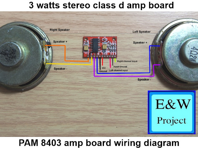
I saw a comment on my youtube video that he want to connect condenser microphone directly to pam8610 amplifier board. However, if he needs to connect condenser microphone to any amplifier board he must bias and amplify the signal before.
Now let's start!!!
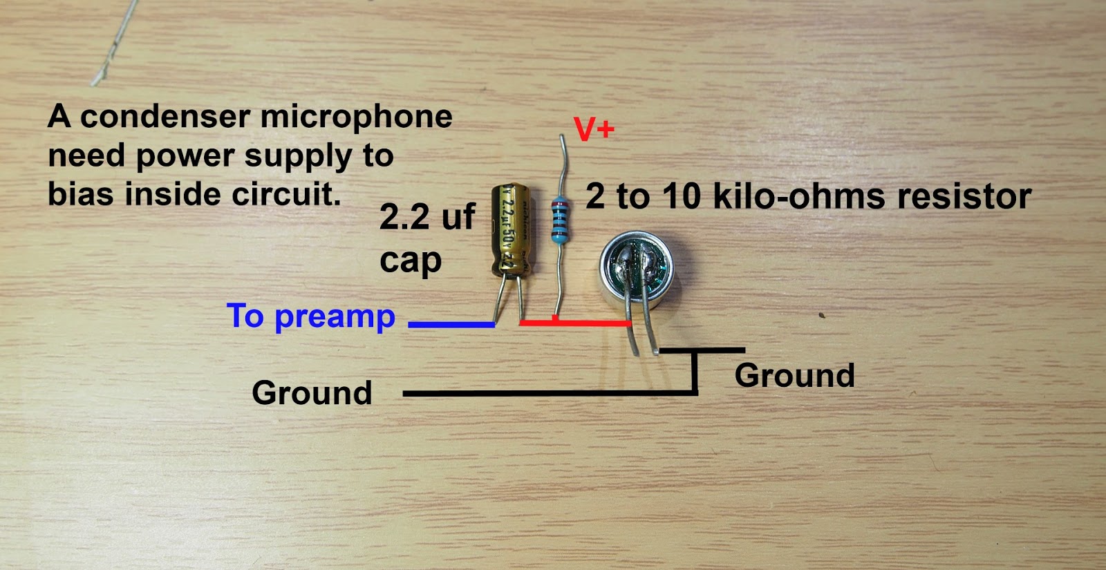
Condenser microphone need a power supply to bias circuit inside that why we need specific preamplifier for it. You need two electronic component to make condenser microphone to operate
1. 2 to 10 kilo-ohms resistor
2. Capacitor uses to blocking dc current to preamplifier
See picture below for better understand.
--------------------------------------------------------------------------------------------------------------------------
Above picture shows how to bias opamp for single power supply (V+ and Ground)
R1 and R2 divide voltage to 1/2 power supply I use 2x 20 kilo-ohms resistors
R3 use to set input impedance I use 10 kilo-ohms resistor so the voltage on non-inverting opamp input is half of power supply.
--------------------------------------------------------------------------------------------------------------------------
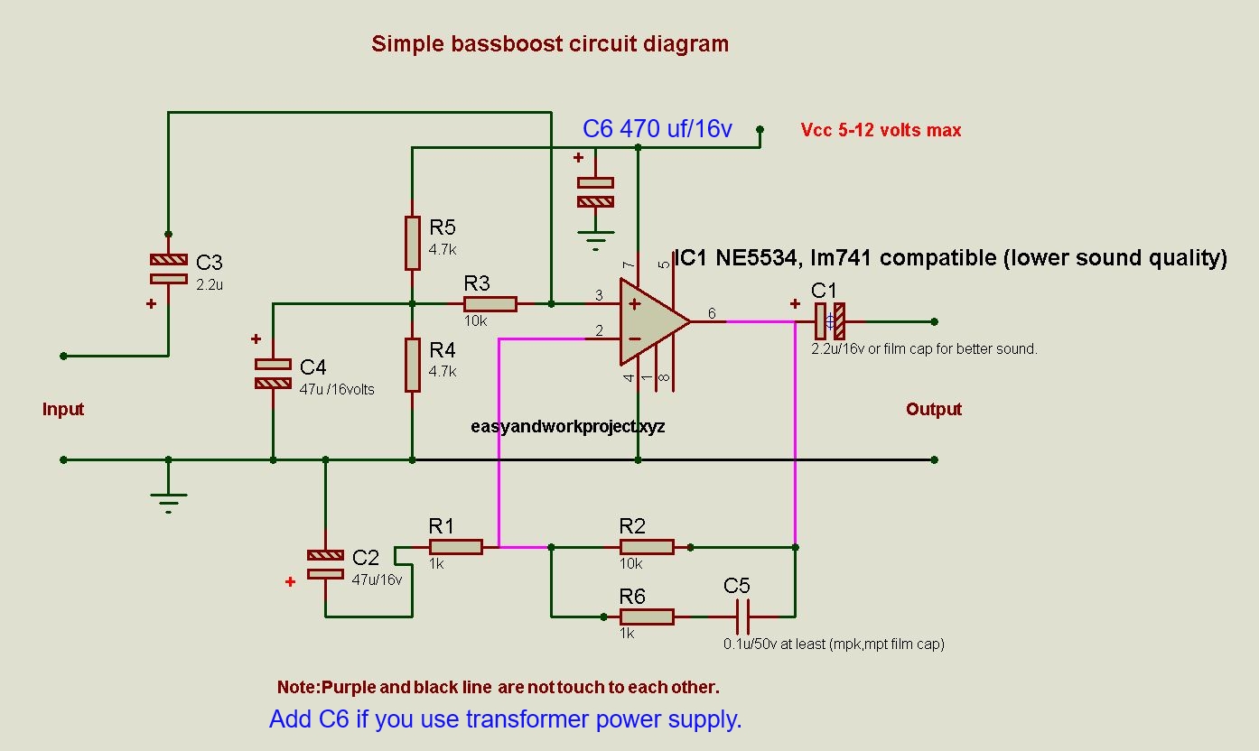
The above picture shows the feedback part of the opamp we use them to set amplifier gain but you need to remember if you increase gain the opamp bandwidth will decrease so I set the gain for this preamplifier to around 21 times.
The formula for noninverting operation feedback is 1+ (R1/R2) The R1 feedback from the output and R2 connect from inverting input to the ground, The feedback also needs a capacitor (C1) to block any dc current to the ground.
--------------------------------------------------------------------------------------------------------------------------
You also need DC blocking from preamplifier output to an amplifier board. Like an image above.
List of components:
IC ne5534R1, R4 20 Kilo-ohms (See how to read resistor color code here)
R2, R3 10 kilo-ohms
R5 10 kilo-ohms
R6 500 ohms
C1 2.2 uf/16 volts ( C1 can replace with MKP type capacitor for better sound)
C2 0.1 uf/60 volts ceramic or mks,MKP cap (lower value increase high-frequency respond)
C3 2.2 uf/16 volts (C3 also can replace with MKP type capacitor for better sound)
C4 10 uf/16 volts (can use 100 uf/16 volts for better low-frequency response)
power supply 5 - 12 volts
 |
| electret microphone schematic diagram |


Can i replace ne5534 with ha741/lm741? & Why ne5534 is better than 741? Answer As simple as possible..
ReplyDeletelm741 high frequency respond is poor, you can hear the different easily.
Deletehow the sound quality and gain is
ReplyDeleteSound quality is good(depending on the mic quality) and voltage gain is 20 times (40 Db).
Delete