How to make a simple audio pre-amplifier
I saw a comment on my video that he wants a high-gain audio amplifier (1000 times or 60 dB voltage gain!!!). However, most commercial power amplifier IC has a maximum fix gain of around 200 times (lm386) which is far from 1000 times voltage gain, and the problem when you make a high gain amplifier is the high-frequency roll-off problem.
The solution to the problem is making a pre-amplifier that has very low distortion, and wide bandwidth, and it can amplify audio signal around 10 times or 20 Dbs and send the audio signal to a power amplifier (the power amp IC he uses is tda7052 that has 40 dB or 100 times voltage gain). When combining the voltage gain of the two amplifiers, he will get 1000 times the voltage gain audio amplifier!!!
The method is easy and uses minimum electronic components
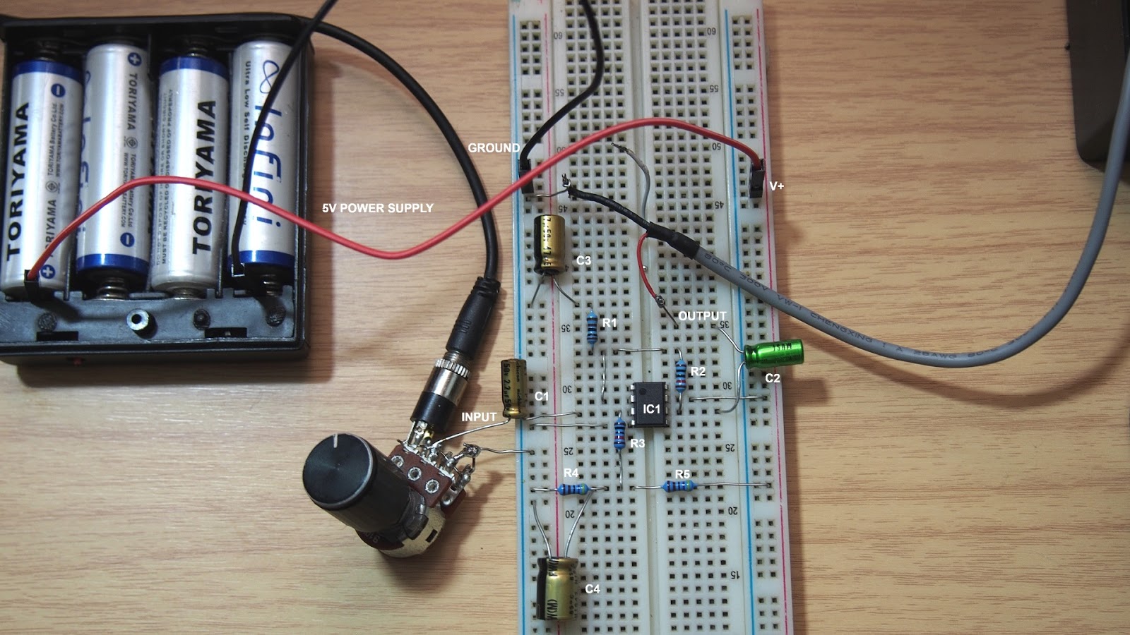 |
| Breadboard wiring |
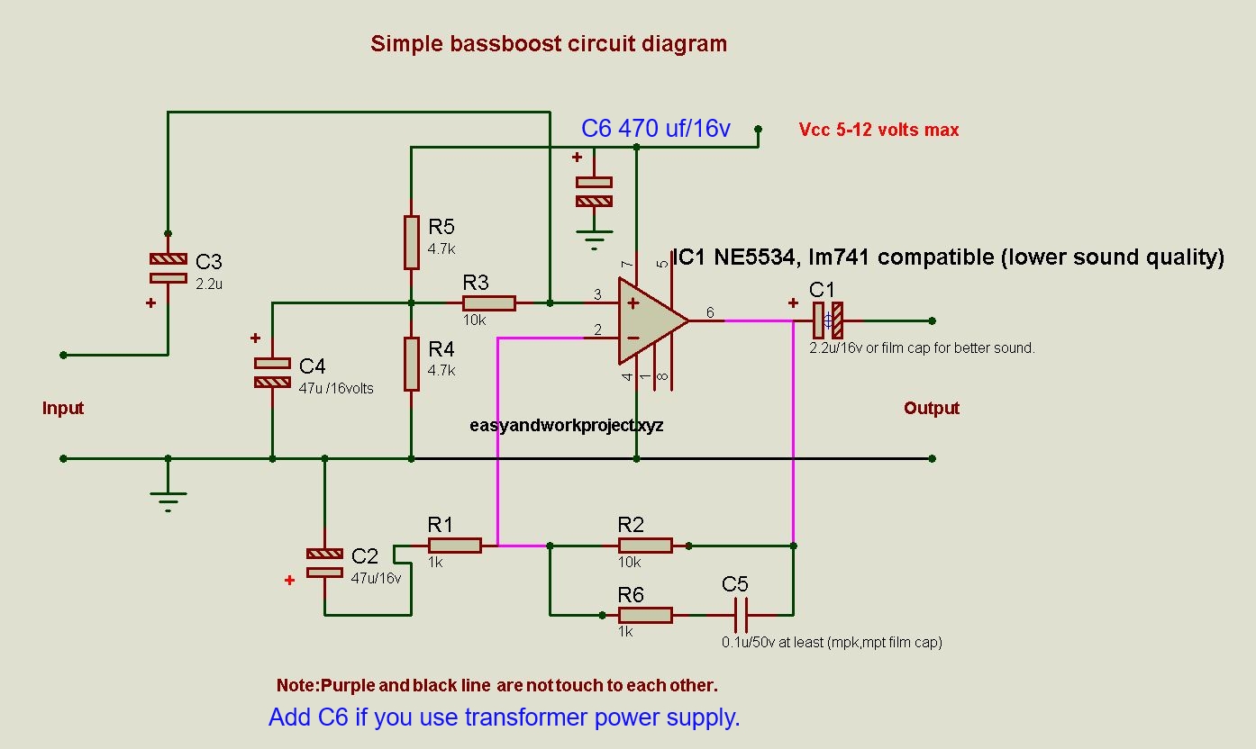
Audio preamplifier circuit diagram.
Electronics component list:IC 1 = NE5534(op amp ic)
R1, R2, C3 are amplifier gain control by negative feedback, the formula is Gain = 1 + (R2/R1)
R1 = 1 kilo-ohm
R2 = 10 kilo-ohms
C3 = 47 uf/16 volts
R3, R4, R5, C4 are opamp input voltage bias. R4 and R5 divide voltage to 1/2 power supply. C4 use to filter hum from a power supply if you use a transformer as a power supply
R3 = 10 kilo-ohms (same value as R2 is fine)
R4,R5 = 4.7 kilo-ohms
C4 = 100 uf/16 volts
C1, and C2 are DC-blocking capacitor
C1, C2 = 2.2 uf/16 volts
This circuit uses a single power supply so it is good for battery operation (voltage less than 12 volts)
The minimum voltage for stable operation is 5 volts so this pre-amplifier can operate by USB port as a power supply.
An input and an output signal use the same ground and must use a dc blocking capacitor.
If you use a transformer power supply instead of a battery, you must use as DC smoothing capacitor between Vcc(+) and ground, the minimum value of the cap is 470 uf/16 volts.
The video below shows you step by step guide and test.
If you have any questions, feel free to ask in the comment section below.
Enjoy the hobby world!!!



Out of all your circuits,you still havent designed an Audio amplifier(20Hz-20kHz) that shows calculations for a gain of more than 20dB and Signal distortion of less than 10%
ReplyDeleteThe ne5534 @ gain 100 (40 dB) produce lower than 10 % THD already. Change R1 to 100 ohms and C3 to 470 microfarads.
DeleteFormula : Gain = 1 +(R2/R1)
Remember, this is only pre-amp part, combine with commercial power amp IC the gain may increase up to 10,000 time and very sensitive to radio signal and environment electromagnetic field, that is the reason I don't make the audio amplifier gain higher than 20 dB.
However, I plan to make low power (1-10 watts range) discrete audio amplifier with mosfet or transistor, stay tune.
How can i calculate signal distortion for a circuit?
ReplyDeleteFind it here.
Deletehttp://www.ni.com/white-paper/3401/en/
Are all the caps listed as electrolytics?
ReplyDeleteYes, but you can change C1 and C2 to bi-polar cap or better cap.
Delete