How to make a DC power supply for your amplifier
Hello, today I will show you how to make a DC power supply for your amplifier project. An audio amplifier normally needs DC power supply to feed it so you need to know how to make it if you want to make a good amplifier.
Now, let's start.
1. Find your amplifier's recommended voltage.
I use TA2024 amplifier board, the amp board recommends voltage is 8.5 - 13.2 volts so I need a DC power supply that output voltage does not exceed 13.2 volts.
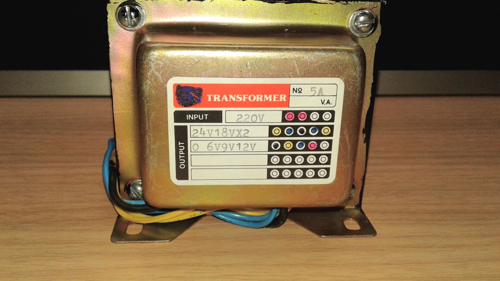
2 Find the right transformer for your project.
When you convert AC to DC with full bridge diode rectifier, the DC voltage increase around 1.4142 - 0.6 volts from an AC input when DC output doesn't connect to a load. I found the formula on the internet and it is AC x 1.4142 only but it was not same as I measured because the DC output voltage decreases around 0.6 volts. The transformer on the above picture provide 9.65 volts AC without connecting to a load, the voltage will drop when you connect to a load.
So the formula is DC out = (ACrms X 1.4142) -0.6 volts
DC out = (9.65 X 1.4142) - 0.6
DC out = 13.04 volts
See real life measure:
The DC output voltage is almost the same as the formula. Remember, the DC output voltage will be drop when connecting to a load.
3. Find Ampere rating your project needs.
Ampere is the most important part when you want to make an amplifier and the formula is
(√ amplifier output/speaker resistance) X 1.4142 for an audio amplifier.
Let's calculate.
(√ 15 / 4) X 1.4142 = 2.78 Ampere x 2 (two channel) = 5.48 A if you add lost from an output of an amplifier (around 10 %) = 5.48 + .548 A
So 6 Amperes is the best for this project but I only have 5 A transformer and it is ok for TA 2024 amp board (The smoothing capacitor will supply instant peak output current to the amp board).
The best transformer's output current is infinity but you can not find it in real life.
4. Connect AC output to a bridge diode rectifier.
Bridge diode rectifier filter AC to DC voltage so it is the important part of this DC power supply circuit.
I use bridge rectifier IC because it is easy to solder, I can solder the IC directly to the diode without a PCB.
5. Connect DC smoothing capacitor.
I use bridge rectifier IC because it is easy to solder, I can solder the IC directly to the diode without a PCB.
5. Connect DC smoothing capacitor.
You can calculate smoothing capacitor value for full bridge diode rectifier by this formula
C = I/ (2 x F) x Vpp
or
V ripple = I/ (2 x F) x C
C = capacitor value in Farad unit
1 Farad = 1,000,000 microfarad (uF)
I = a load current in Ampere unit
1 Ampere = 1000 mAh
F = AC line frequency in Hz unit
Note: The formula uses 2 F for Full wave rectifier, use F for half wave rectifier.
Vpp is the ripple voltage your circuit can withstand and work without any problem, the lower the ripple voltage the cleaner DC output, but you need a bigger capacitor too.
I saw some DIY lover on the internet said that
Pioneer A-77x - 100wpc @ 8; 16,400uf per channel (8200x2); 164uf per watt
Onkyo TX-7000 - 90wpc @ 8; 22,000uf per channel (22000x1); 244uf per watt
1 watt @ 8 ohms need peak current around
√ 1/8 = 0.353 Ampere
1 watt @ 4 ohms (TA2024 can drive 4 ohms)
√ 1/4 = 0.5 Ampere or around 1.4142 times x 8 ohms load current
So, in this case, you need to multiply capacitance value if you want to copy capacitance value from the audio company. let's say that TA 2024 use around 30 watts(15 watts x 2) @ 4 ohms(THD 10 %).
If you want to use Onkyo TX- 7000 capacitance value, around 244 uf per watt @ 8 ohms
Convert capacitance value for 4 ohms load
244 uf x 1.4142 = 345 uf per watt
345 uf x 30 watts = 10,350 uf
The capacitance value is a little bigger but it will make TA 2024 amplifier stable but I use 2200 uf (around 1/5 value of Onkyo TX-700) and sound quality still good without any hum noise. However, I didn't play the amplifier to full power in the video below so sound may lack clarity if I play at full power!!!
Now, it is a test time.
C = I/ (2 x F) x Vpp
or
V ripple = I/ (2 x F) x C
C = capacitor value in Farad unit
1 Farad = 1,000,000 microfarad (uF)
I = a load current in Ampere unit
1 Ampere = 1000 mAh
F = AC line frequency in Hz unit
Note: The formula uses 2 F for Full wave rectifier, use F for half wave rectifier.
Vpp is the ripple voltage your circuit can withstand and work without any problem, the lower the ripple voltage the cleaner DC output, but you need a bigger capacitor too.
How much capacitance that some audio amplifier company use for their real product?
I saw some DIY lover on the internet said that
Pioneer A-77x - 100wpc @ 8; 16,400uf per channel (8200x2); 164uf per watt
Onkyo TX-7000 - 90wpc @ 8; 22,000uf per channel (22000x1); 244uf per watt
1 watt @ 8 ohms need peak current around
√ 1/8 = 0.353 Ampere
1 watt @ 4 ohms (TA2024 can drive 4 ohms)
√ 1/4 = 0.5 Ampere or around 1.4142 times x 8 ohms load current
So, in this case, you need to multiply capacitance value if you want to copy capacitance value from the audio company. let's say that TA 2024 use around 30 watts(15 watts x 2) @ 4 ohms(THD 10 %).
If you want to use Onkyo TX- 7000 capacitance value, around 244 uf per watt @ 8 ohms
Convert capacitance value for 4 ohms load
244 uf x 1.4142 = 345 uf per watt
345 uf x 30 watts = 10,350 uf
The capacitance value is a little bigger but it will make TA 2024 amplifier stable but I use 2200 uf (around 1/5 value of Onkyo TX-700) and sound quality still good without any hum noise. However, I didn't play the amplifier to full power in the video below so sound may lack clarity if I play at full power!!!
Now, it is a test time.



Comments
Post a Comment