The simplest fan speed control circuit diagram
Hello, today I will show you how to make a simple fan speed control by just 3 electronic components
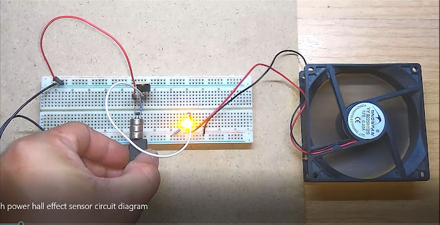
I use only 3 parts One is a 10 kilo-ohms resistor
An IRF540N NPN MOSFET and a 10 kilo-ohms potentiometer
No heatsink require for less than 2 A load
I use a MOSFET instead of a transistor because a MOSFET control input by voltage
so it's easy to bias
Let's start by connecting the resistor to the positive terminal and connect another leg to a MOSFET gate
connect a MOSFET gate pin to a 10 kilo-ohms potentiometer. two resistor works as a voltage divider
connect a MOSFET drain pin to the ground and also connect the potentiometer middle leg to the ground
This circuit use only two legs of a potentiometer
Then connect a source pin to the load negative pin and connect the load positive pin to 12 volt or positive terminal.
See the video below for practical use.


Comments
Post a Comment