lm3914 schematic diagram and test
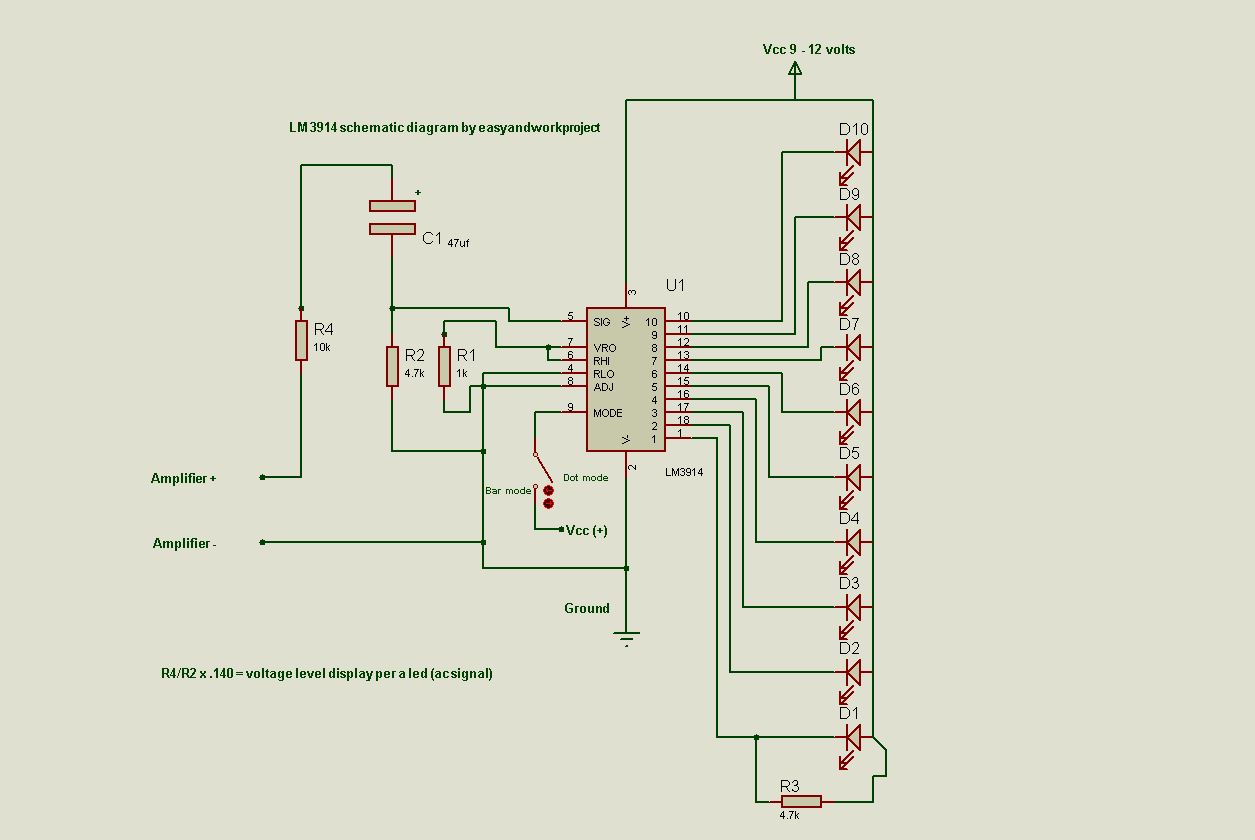
If you want to make a simple VU meter. LM3914 is the best choice for you. It's easy to make VU meter or 10 dot/bar DC level meter with lm3914.
lm 3914 can withstand +-35 volts input without any damage so you can make VU meter even you are new in electronic DIY.
The circuit uses minimal component to make the job done.
List of component:
R1 = 1 kilo-ohms
R2,R3 = 4.7 kilo-ohms
R4 = 10 kilo-ohms
ic = lm 3914n-1 (lm3914)
C1 = 4.7 uf at least to 47 uf (better bass respond)
10 LEDs red,green,yellow,orange or whatever you want
9 - 12 volts DC power supply
LM3914 schematic diagram
Lm3914 VU meter video, the video show step by step guide and circuit explanation.



👌 Thanks for great idea for me. Actually I'm not expart. But I'm really interested. Actually i want to build a music vu meter. & I did it by using LM3914 IC with a basic circuit diagram. & I found actually what i want. Sorry for my bad English.
ReplyDeleteYou're welcome. I'm not an English expert so don't worry about it
DeleteSir i need a little help from you. 1➡I don't have 1n4048 diode. Can i replace with 1n4148???
ReplyDeleteNo problem, you can use 1n4148.
DeleteThanks again & again.
ReplyDelete➡I want to add more then 10 led using 1 lm3914. Is it possible?
I'm not sure.
Delete