3 ways touch selector switch circuit diagram
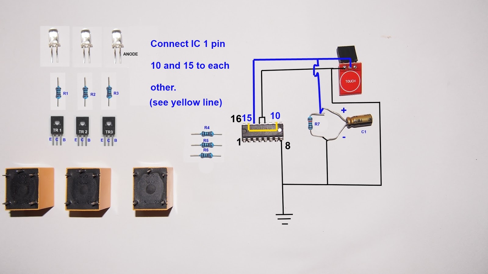
Hello, today I'm going to show you how to make a 3 ways touch selector switch. This electronic project makes you switch 3 electronic loads (light bulb, electric fan) to switch on/off by touch the sensor.
Let's start!!!
Components you need:
R1,R2,R3,R4,R5,R6 are 1 kilo-ohms resistor
R7 = 10 kilo-ohms
IC 1 = CD4017BE
Relay 1,2,3 are 5 volts relay
TR1,2,3 are BD139 npn transistors
led 1,2,3 = low power led red,green,blue
C1 = 2.2 uf T1 = touch sensor
This circuit use 4.5 - 5 volts power supply, so you can use 3 AA battery, USB power, or 4 AA rechargeable battery as you need. Use power supply over 5 volts not make circuit broken but the relay must be changed to 12 volts power supply type and you must use 5 volts regulator for touch sensor module.
This circuit use 4.5 - 5 volts power supply, so you can use 3 AA battery, USB power, or 4 AA rechargeable battery as you need. Use power supply over 5 volts not make circuit broken but the relay must be changed to 12 volts power supply type and you must use 5 volts regulator for touch sensor module.



How can i make fan regulator using two touch sensor ?? Through up and down touch keys.
ReplyDelete