Posts

Humidity sensor with led alarm | Arduino project
Image
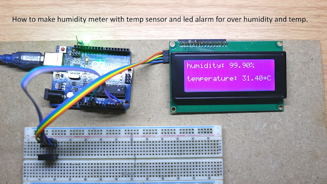
This page contains Arduino Humidity sensor with led alarm source code. This project is good for someone who wants to make a humidity meter or hygrometer with led alarm if humidity and temperature over a threshold. It's easy to make and doesn't require an external power supply, just use power from an Arduino UNO R3 board (USB power compatible with this project). Electronic components list: 1 x Arduino Uno R3 1x 20 x4 I2C LCD display 1 x AM 2320 humidity/temp sensor 1 x 5 mm led ( 2 x if you plan to use led for pin 13 instead built-in led) 1 x 1000 ohms resistor ( 2 x if you plan to use led for pin 13 instead built-in led) Any USB power adapter, 500 mA current at least. Here is the Arduino code: AM 2320 library  https://github.com/hibikiledo/AM2320 LCD display i2c library  https://github.com/fdebrabander/Arduino-LiquidCrystal-I2C-library #include <Wire.h> #include <AM2320.h> #include <LiquidCrystal_I2C.h> LiquidCrystal_I2C lcd(0x3...
How to make an emergency led light

Image
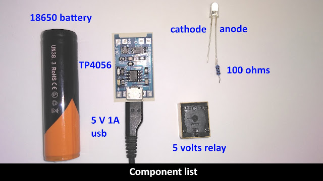
This video shows you how to make an emergency light, it is the very important thing when a 110/220 AC power failure. This circuit will make your life better!!! This emergency led light project use minimal electronic components and can work over 10 hours and recharge automatically. The circuit uses USB power supply so you can use old smartphone adapter as power supply, 5 volts, and 1 Ampere is the minimum required for this circuit. Electronic component list: 1 x  18650 Li-ion battery 1 x TP 4056 Li-ion battery charger module 1 x 5 volts relay 1 - 10 x 100 ohms resistor 1 - 10 x low current white led (another color is ok but white led is the best) 5 volts 1 Ampere USB type c adapter Real electronic components picture After you got all the electronic components I listed above, it's time to make the circuit by watching my video. This circuit has a very long life, all you need to change is 18650 battery(many years). You may need to recharge the batter...

How to build high current hall effect sensor

Image
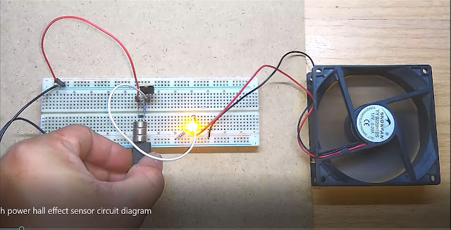
I published hall effect sensor circuit diagram and my audience asked me how to make a hall effect sensor that has a high current capability, so I made it for him and for all of you who want to build high current hall effect sensor. Normally, hall effect sensor used for detect magnetic field and send output to a microcontroller, that means any hall effect sensor doesn't need to have high current output. However, if you want to drive motor or any high current device without a microcontroller, this circuit is the best for you. List of components for this project: 1 x IRF 9540N (P channel MOSFET) 1 x A3144 hall effect sensor 1 x 1 kilo-ohms resistor 1 x 10 kilo-ohms resistor optional (use for led indicator) 1 x 1 kilo-ohms resistor 1 x White, red, blue or any other low current led Note: all resistor for this circuit is 1/4 watt, 20 % tolerance is ok with this circuit. The principle of this circuit: When hall effect sensor detects magnetic ...

How to make an IR toggle switch

Image
Hello, today I will show you how to make an IR toggle switch with Arduino and a Mosfet, it has far more detection range than capacitive touch device and easy to build. The circuit is easy to use and use minimal components to make a job done, now let's start Components list: R1 = 100 ohms resistor R2 = 470 Kilo-ohms resistor R3 = 10 Kilo-ohms resistor R4 =1000 ohms or 1 kilo-ohms IR1 = infrared led IRR1 = infrared receiver led = low forward voltage led, you can find it on any electronic part store Tube1 =Shrink tubing 1 x irf9540n p-type Mosfet If you have the components I list ready, it's time to upload this code to your Arduino UNO r3 /* switch  *   * Each time the input pin goes from LOW to HIGH (e.g. because of a push-button  * press), the output pin is toggled from LOW to HIGH or HIGH to LOW.  There's  * a minimum delay between toggles to debounce the circuit (i.e. to ignore  * noise).    *  * David A...

how to make an automatic faucet

Image
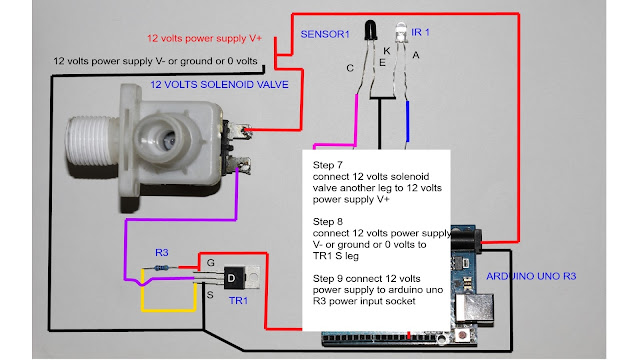
Now you will not forget to close your faucet or waste water when you pick a soap to wash your hand or face. This project shows you how to make an automatic faucet, you can even use the faucet that water valve damage because of this circuit use solenoid valve to control water. Electronic components you need: 1 Arduino Uno R3 1 TR1 = IRF 540n N channel MOSFET 1 Sensor1 = IR sensor 1 IR1 = IR led R1 = 10 kilo-ohms R2 = 100 ohms R3 = 4.7 kilo-ohms 1 12 volts solenoid valve 12 volts 1 Ampere adapter The Arduino code is very simple and you don't need to load any special module to make this project works  created 29 Dec. 2008  modified 9 Apr 2012  modified 20 Oct 2017 by easyandworkproject.xyz  by Tom Igoe  This example code is in the public domain.  */ // These constants won't change.  They're used to give names // to the pins used: const int analogInPin = A0;  // Analog input pin that the ir sensor is attached ...

3 ways touch selector switch circuit diagram

Image
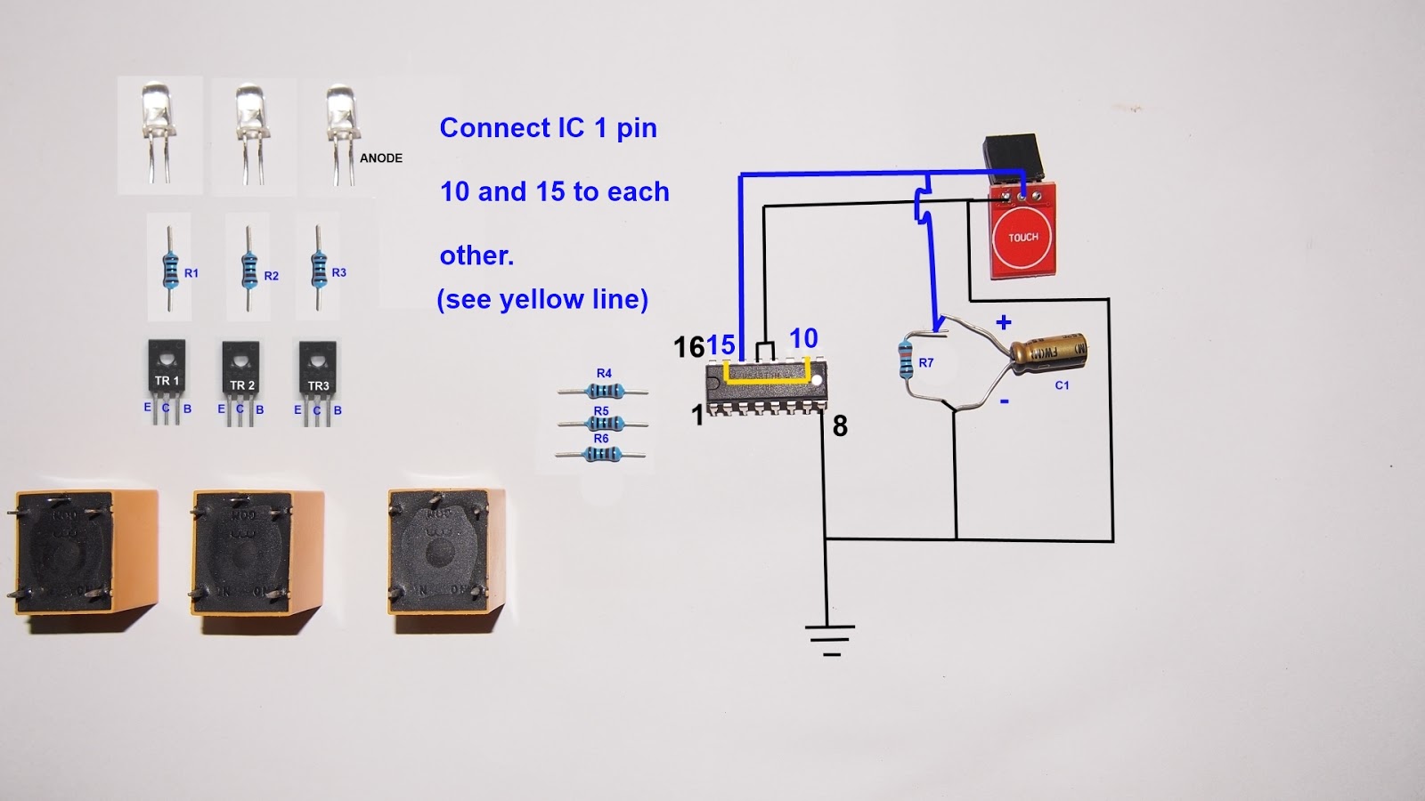
Hello, today I'm going to show you how to make a 3 ways touch selector switch. This electronic project makes you switch 3 electronic loads  (light bulb, electric fan) to switch on/off by touch the sensor. Let's start!!! Components you need: R1,R2,R3,R4,R5,R6 are 1 kilo-ohms resistor R7 = 10 kilo-ohms IC 1 = CD4017BE Relay 1,2,3 are 5 volts relay  TR1,2,3 are BD139 npn transistors led 1,2,3 = low power led red,green,blue C1 = 2.2 uf T1 = touch sensor This circuit use 4.5 - 5 volts power supply, so you can use 3 AA battery, USB power, or 4 AA rechargeable battery as you need. Use power supply over 5 volts not make circuit broken but the relay must be changed to 12 volts power supply type and you must use 5 volts regulator for touch sensor module.  All you need to do next is watching my video below

Combine 3 speakers to one amplifier

Image
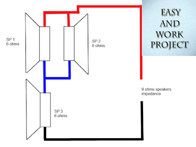
I saw a question in my Youtube video about how to combine speakers for one amplifier unit without making any damage to an amplifier.  An speaker impedance must be match or higher than an amplifier manufacturer specification, if you use lower speaker impedance than an amplifier specification, your amplifier may end up damaged or make a fire when you play loud music. A commercial amplifier can handle between 4 - 16 ohms speaker impedance and maybe lower to 2 ohms for car subwoofer amplifier. but in a question, he asked me how to combine 3 speakers @ 6 ohms load to one amplifier. The simple solution is to make 3 separate amplifiers and share same input, but it makes the circuit more complicated and uses many electronic components. However, if connect all 3 speakers in series, it will make impedance equal to 18 ohms and it makes an amplifier output drop so much. So, I use 2 speakers connect in parallel and series to other speakers like an image below SP 1 and SP 2...

5 watts amplifier TDA7056A wiring diagram

Image
TDA 7056 A is an audio power amplifier IC that has 5 watts output power with 8 ohms speaker and 3 watts with 16 ohms speaker. The IC is simple to wiring and needs only 6 external components to make the amplifier working. TDA 7056A working with a power supply between 4.5 - 18 volts so the IC can use a battery as power supply. if you use more than 9 volts, you need to attach small heat sink to the IC. TDA7056A has a built-in DC volume control so you can control the gain of the amplifier by changing voltage value at DC volume control pin by use a potentiometer. DC volume control makes you connect the audio signal directly to the amplifier input so it makes a sound more transparent and cleaner than a normal amplifier.  The IC has a short circuit protection, over temperature protection, No switch-on/off clicks, ESD protected on all pins, Mute mode (The IC switch mode when DC volume control pin voltage lower than 0.3 volts)  TDA 7056A has a very wide audio bandwidth 20 H...

How to remove scratch coating from mobile phone camera

Image
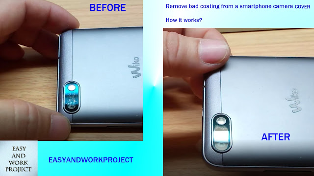
Now a day a mobile phone camera lens cover coating with anti-glare, scratch resistance. However, every coating material can be scratched easily even the smartphone camera coating with scratch resistance material, and it makes the camera quality drop significantly.  The best way to fix this problem is removing the scratches coating off the camera lens cover, but you need to remove it the right way or you may end up make more scratches to the camera lens cover. My instruction is easy to do and make a pleasant result. All tool you need is old sim card adapter and car polishing(no rubbing bead type) You may have a question in your mind that why I use sim card adapter as the rubbing tool. - The simple answer is a sim card adapter made of plastic that softer than commercial cell phone camera lens cover. Please check the video below for the instruction and before and after comparison.

Awesome ideas with inner tire tube

Image
Hello everyone, today I will show you how to save money with old inner tire tube. Next time when you change a tire tube to a new one, you should not put it in a bin ;) See the video below and see how it works.

security door alarm circuit diagram

Image
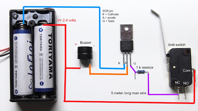
Hello, today I will show you how to make a security door alarm, the door alarm is easy to make and give the best result. The door security alarm provides a very long battery life and easy installation, the circuit use only 2.4 volts to operate so you can power the circuit with 2xAA rechargeable battery or even you can use a lithium-ion battery with auto charging circuit as power supply because the circuit can withstand up to 5 volts power supply.  If you want to change the power supply to 12 volts, you simply need 7805 IC to regulate 12 volts to 5 volts without any problem. You also can use 12 volts Buzzer instead 5 volts Buzzer that I used in the circuit and connect directly to 12 volts power supply (solar charger's output, 12 volts car battery). The SCR (thyristor) in this circuit can withstand current up to 3 A so you can connect 20 Buzzers (estimate 100 milliamp/hour per Buzzer) with one circuit module without making any damage to The SCR. You also can ...

lm3914 schematic diagram and test

Image
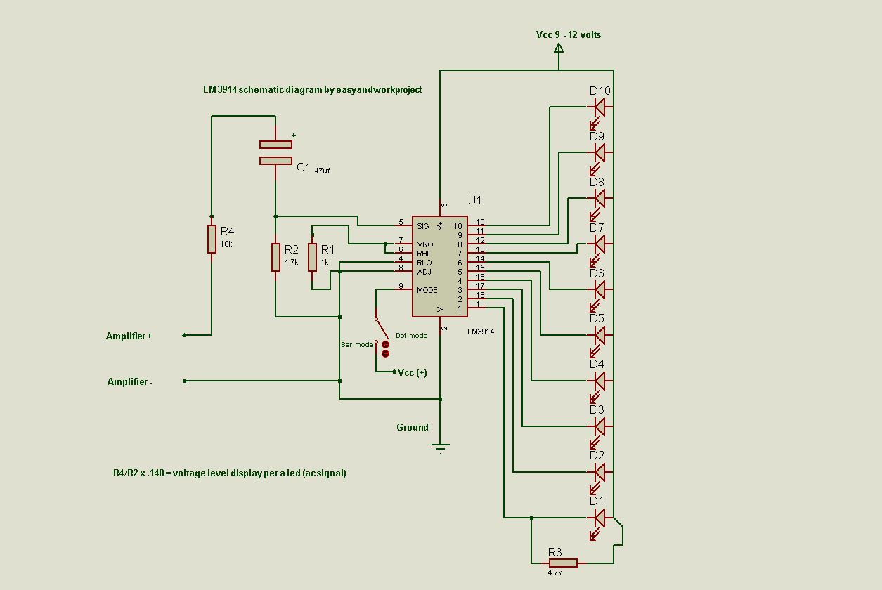
If you want to make a simple VU meter. LM3914 is the best choice for you. It's easy to make VU meter or 10 dot/bar DC level meter with lm3914.  lm 3914 can withstand +-35 volts input without any damage so you can make VU meter even you are new in electronic DIY. The circuit uses minimal component to make the job done. List of component: R1 = 1 kilo-ohms R2,R3 = 4.7 kilo-ohms R4 = 10 kilo-ohms ic = lm 3914n-1 (lm3914) C1 = 4.7 uf at least to 47 uf (better bass respond) 10 LEDs red,green,yellow,orange or whatever you want 9 - 12 volts DC power supply LM3914 schematic diagram    Lm3914 VU meter video, the video show step by step guide and circuit explanation. Now, I add a sine wave rectifier circuit to lm3914, it makes the dot mode more accuracy. Real dot mode VU meter schematic diagram